Repair and Password Reset of Ingrasys Ipoman 1200/1201
I was donated a flaky Ingrasys Ipoman II 1201 Power Distribution Unit (PDU). This article describes how I fixed the power supply by replacing an electrolytic capacitor and subsequently reset the password to factory defaults.
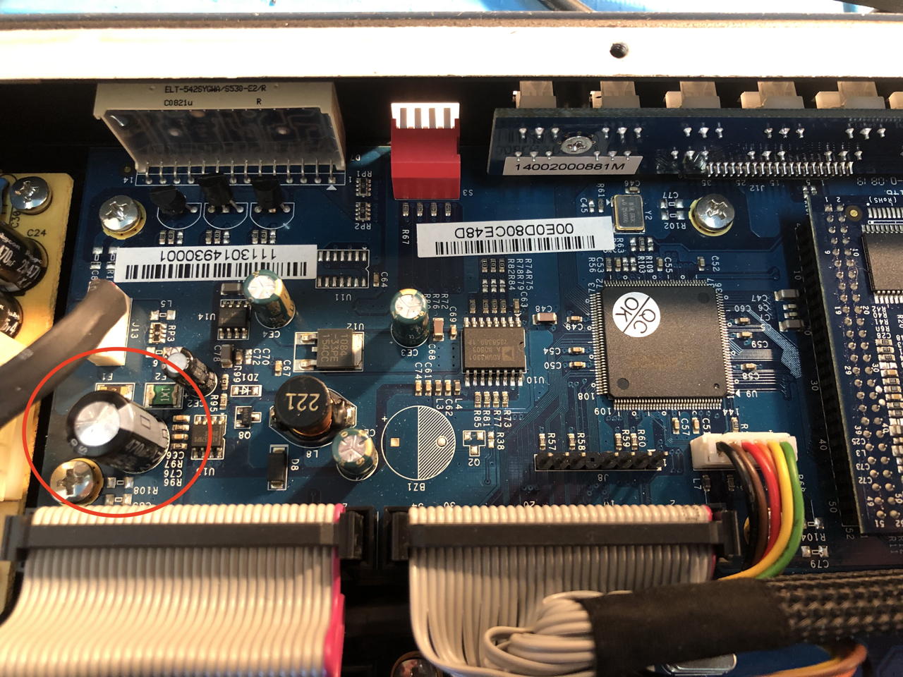
It is quite a common problem nowadays, power supplies break down because of bad electrolytic capacitors. So the first thing I sought after opening up the Ipoman was bulging caps. Sure enough, there was one, right on the logic board power input. Getting the print out was tricky, as there are sub-circuit boards connected to the main controller board.
Replacing the capacitor
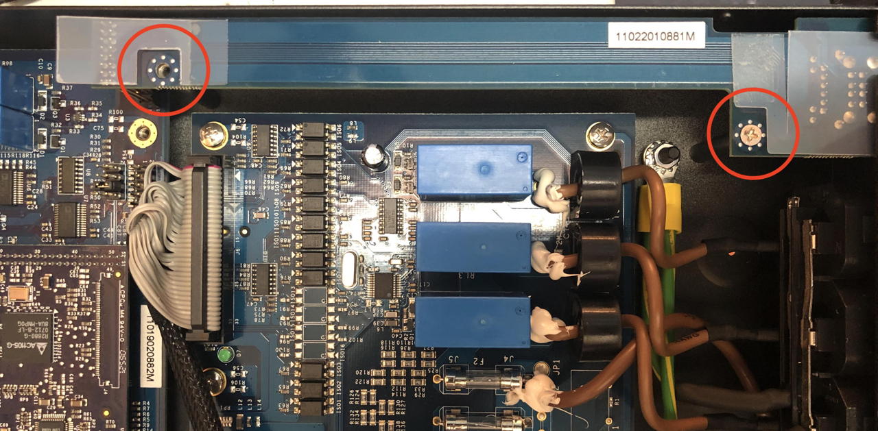
You have to loosen the display board first.
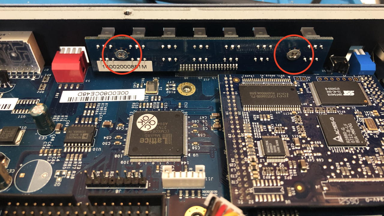
Then you need to remove the console plug board on the right.
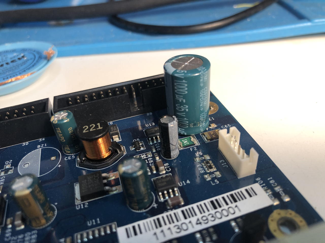
Carefully lift out the controller board and remove the display board. The damaged capacitor is a 470 uF 25V version. However, since electrolytic caps have a lousy accuracy, and I had a 1000uF 35V cap laying around, I replaced it with that value. The desoldering job was difficult as they used non-normal solder. I needed to heat my iron to over 400°C to get it to melt. Even then it was hard to clean the soldering holes. You can also use a copper wire or small drill to clean open the holes.
Put everything carefully back together again and fire up the ipoman: it should start up, have blinkenlights and you should be able to connect to the console on 9600/8N1 or website.
However, there was a small snag, as the benefactor did not benefact me with the admin password of the device.
The manual stated you could reset to factory defaults from the console, but how to get to this console? The internet was of no help.
Password reset
Wherever I looked, I could not find a way to reset to factory defaults. Until a colleague mentioned he used to reset it in the past by pressing reset while starting up. Now I had a handle, but it did not work so easily.
I tried
Power cable off - press reset - power on - keep reset pressed for another 10 seconds: nope, it starts up normally. I tried the same but for 30 seconds, remembering some older internet routers. Also no go.
Then I set the blue switch 1 and 2 on the front panel to ON. Next to the reset hole. After startup the following appeared in the console:
USHA AGENT BOOT CODE VER 6.12
RELEASE DATE: 24/05/07

KID=0F     BID=22
100MHz CPU Detected
Real Time Clock Present
NIC IO Base FE00
8192KB Memory Installed,  8192KB Flash ROM Installed

Jumper and DIP Switch Status: JMP1-OFF JMP2-OFF SW1-ON SW2-ON
Clear Password Jumper not installed

BIOS Shadowed
Wait, Clear Password Jumper?
I opened up the case again and start looking for jumpers. There are three places where you can put jumpers. So it was a bit of a guess. For starters I tried removing jumper 3 on J4. This didn’t work.
Then I installed a jumper on position 1 on J4. There is a ▲ underneath the position.
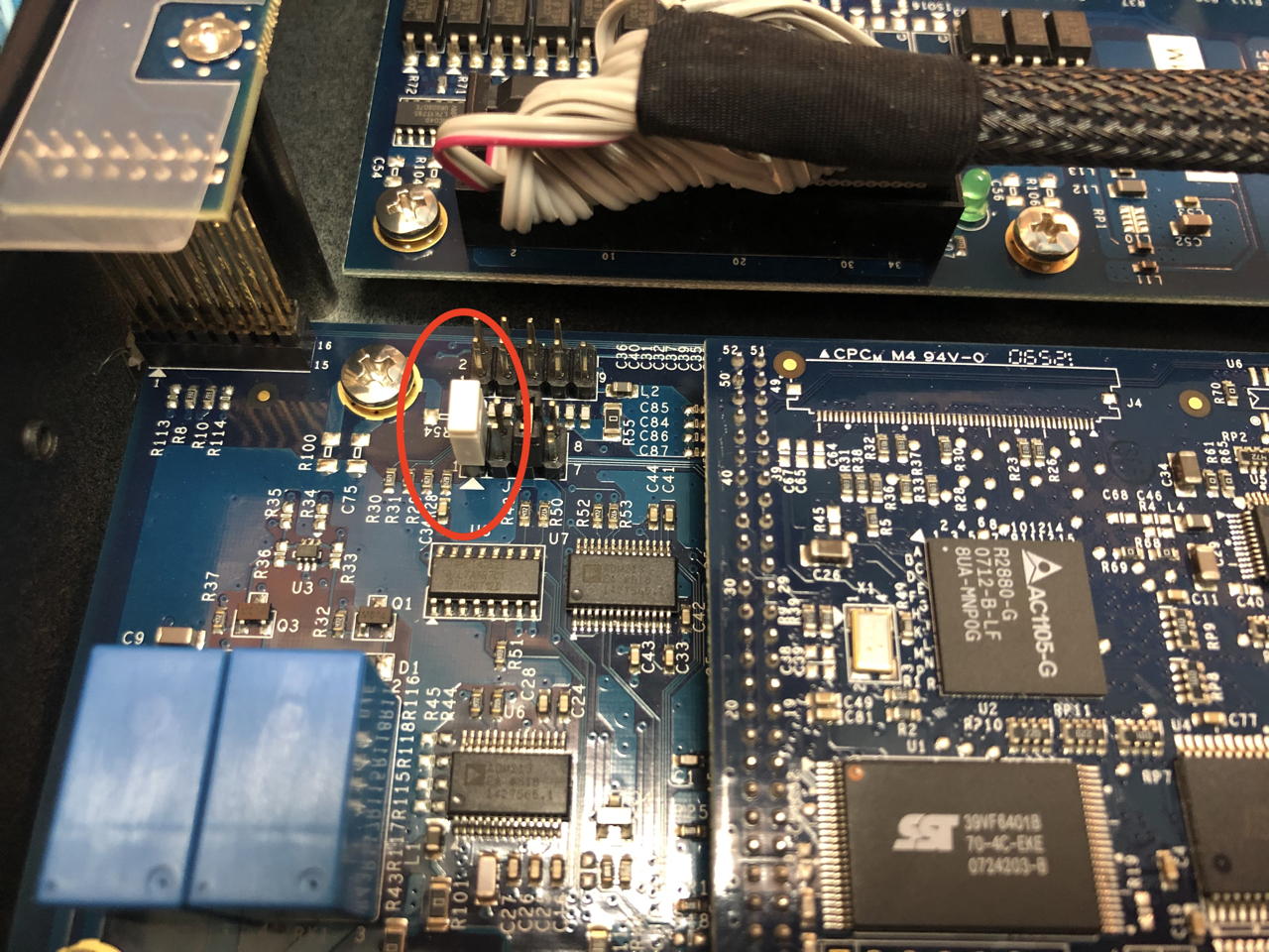
I booted up the machine and presto!
Jumper and DIP Switch Status: JMP1-ON JMP2-OFF SW1-ON SW2-ON
Clear Password Jumper installed
Then you enter a hardware test menu:
1) CPU SELF TEST
2) SDRAM MEMORY TEST
3) NIC INTERNAL TEST
4) FLASH ROM TEST
5) LED BLINKING TEST
6) READ JUMPER AND DIP SWITCH STATUS
7) NIC EXTERNAL LOOPBACK TEST
8) SELECT DIGITAL OUTPUT TO ON/OFF
9) FLASH FUNCTIONALITY TEST
A) SELECT OUTLET TO SWITCH ON AND SHOW ON THE 7SEGMENT
B) SHOW DAISY CHAIN DIP SWITCH STATUS
C) INLET TEST
E) ADE TEST
R) RTC TEST
L) RUN ALL TEST
I think it’s prudent to run all test on second hand equipment. My unit was fine.
You cannot use the pdu with the jumper installed; you have to remove it. When you startup with the jumper removed and the switches back to the OFF position, the machine starts up normally, and you can access it using the default password from the user manual ‘admin’.
+============================================================================+
|                 [ PDU Configuration Utility Main menu ]                    |
+============================================================================+
   1. PDU Configuration
   2. Outlets Control
   3. Digital Output Control
   4. EMD Control
   5. Access Control Table
   6. Trap Receiver Table
   7. Reset Configuration To Default
   8. Restart PDU
   0. Exit
Hurray! You can now set your own password, configure the IP number etc.
I hope this helps someone besides me.